Air Contactor for “As Passive as Possible”, Methane Powered DAC
“The Trees are Back!” and “I’ll take flying saucers for 100, Alex”.
My work in CO2 removal began as an exploration of how to leverage 3.8 billion years of biological evolution to remove gigatons of CO2 from the air. I specifically wanted to build a machine that used biological technologies, strategies, and chemistries to remove CO2 from the environment using as little energy as possible.
This project evolves as I learn about nature and various technologies. Like some living organisms, this project uses a circulating aqueous solvent to absorb CO2 from the air. The solvent is regenerated as CO2 is captured. The chemistry for CO2 absorption and solvent regeneration is well understood.
My current focus is to get CO2 from the air and into the solvent in a meaningful, scalable, and low-energy way. This essay will document various aspects of the air contactor.
One of the philosophies guiding my efforts is to "Take what nature willing gives". This philosophy is in stark contrast to most other CO2 capture technologies.
Besides creating an energy-efficient CO2 capture technology, my current goal is to create a DAC system that can be powered using methane. This goal is unpopular now, but I firmly believe it is very important. Thermodynamics makes it clear that renewable energy must be utilized to reduce current CO2 emissions. CDR that needs carbon-free energy will have to wait, perhaps decades.
With this goal in mind and the fact that a unit of methane has a limited amount of energy, my work fully considers how every Joule is consumed. My analysis of my CO2 capture chemistry shows a unit of methane, 465m3 STP, can capture and sequester its own CO2 emission (1 ton) and 4 additional tons of CO2 from the air.
Klaus Lackner has written extensively about Passive Direct Air Capture. He expresses the benefits of NOT using fans better than I ever will. I refer you to his work, which emphasizes that avoiding fans is not the only consideration. Avoiding the consequences of Sherwood's rule is equally important.
Klaus_Lackner_CCE_PanelDay2 - Cleaning up Climate Change A Business Opportunity (energy.gov)
The design of this air contactor begins by studying air contactors found in nature. The most famous air contactor is the lung. This organ has a very high functional surface area contained within a volume. While the physical structure of the lung is impossible to build, the high functional surface area is an important goal to achieve.
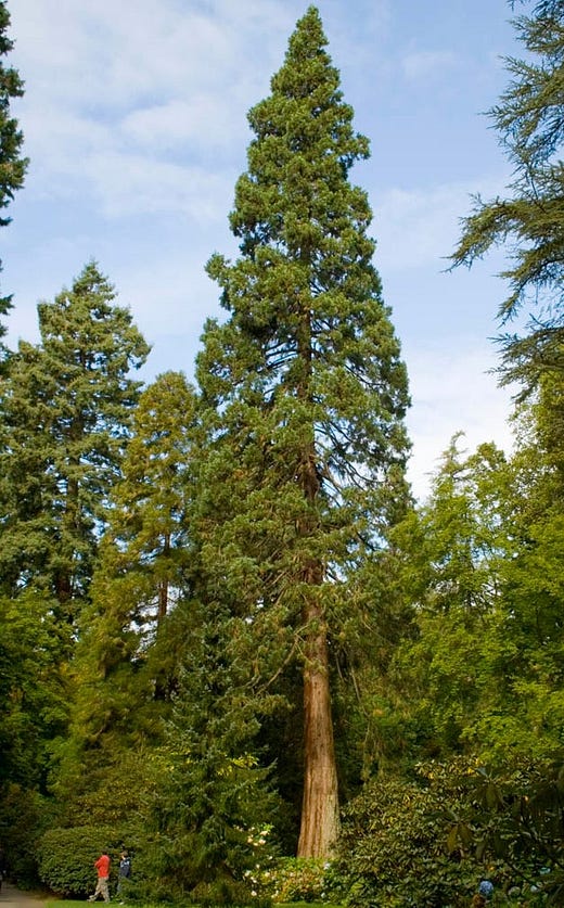
Another obvious air contactor is the tree. The Redwood tree provides an ideal structure to replicate.
Tall Redwood trees inspire passive Direct Air Capture
This tree is tall, and the leaves provide the high functional surface area in contact with the air. Since we must remove gigatons of CO2 from the air, a forest of CO2-capturing trees (CCT Trees) will be created to operate at a large scale.
Be aware that all numbers are illustrative and included to help share the model. Every number is an independent parameter and a variable in the software model. Once complete, the software will allow for changing the parameters to determine effective and optimal performance.
We have three dimensions, and my air contactor design uses all of them. I model the CCT tree contactor to be 105 meters tall, but I expect the trees to exceed 300 meters in practice.
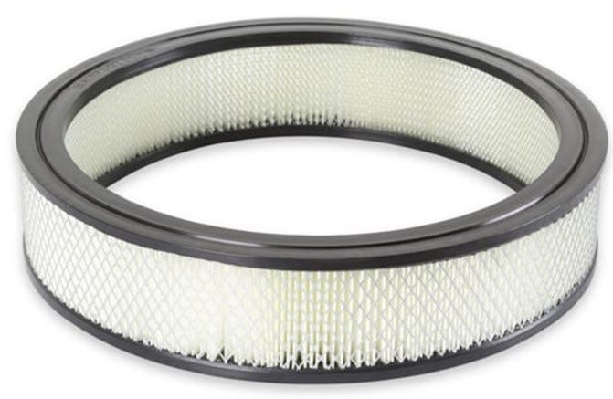
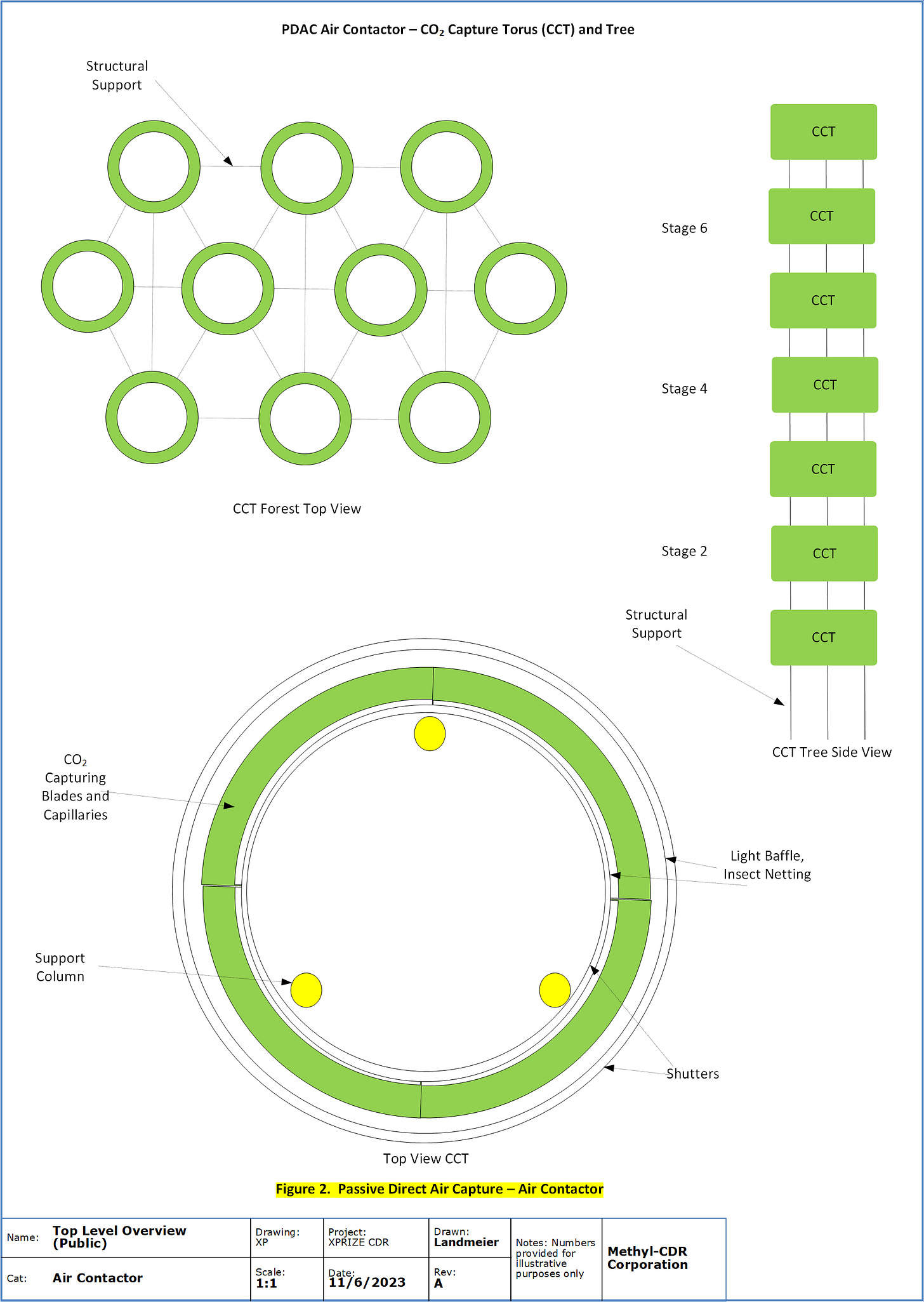
The structural unit of CO2 capture is the CO2 Capturing Torus (CCT). Visually, the CCT looks like a carburetor filter.
“As Passive as Possible” air contactor inspired by a “Holley Carburetor Air Filter”!
The actual CCT is a torus that is 5 meters tall, the ring is 2m wide, and the inner hole is 10m in diameter. Radially positioned blades replace the pleated part of the filter. Each blade is 4m tall, 1m deep, and 8mm wide. Each CCT operates independently of all other CCTs in the tree. The inputs are power and water. The output is high-grade CO2 gas.
The hole's circumference is 31.4m, and the blades will be placed 10mm apart. This positioning allows the CCT to contain 3140 blades.
The specifics of the blade are beyond the scope of this essay. They are best visualized as having 100 tubes (CO2 capillaries) positioned along the depth of the blade. The CO2 capillaries are 8mm in diameter and are spaced 10mm apart. Each capillary is 4m long and has an effective surface area of 0.1 m2. This gives the blade a surface area of 10m2.
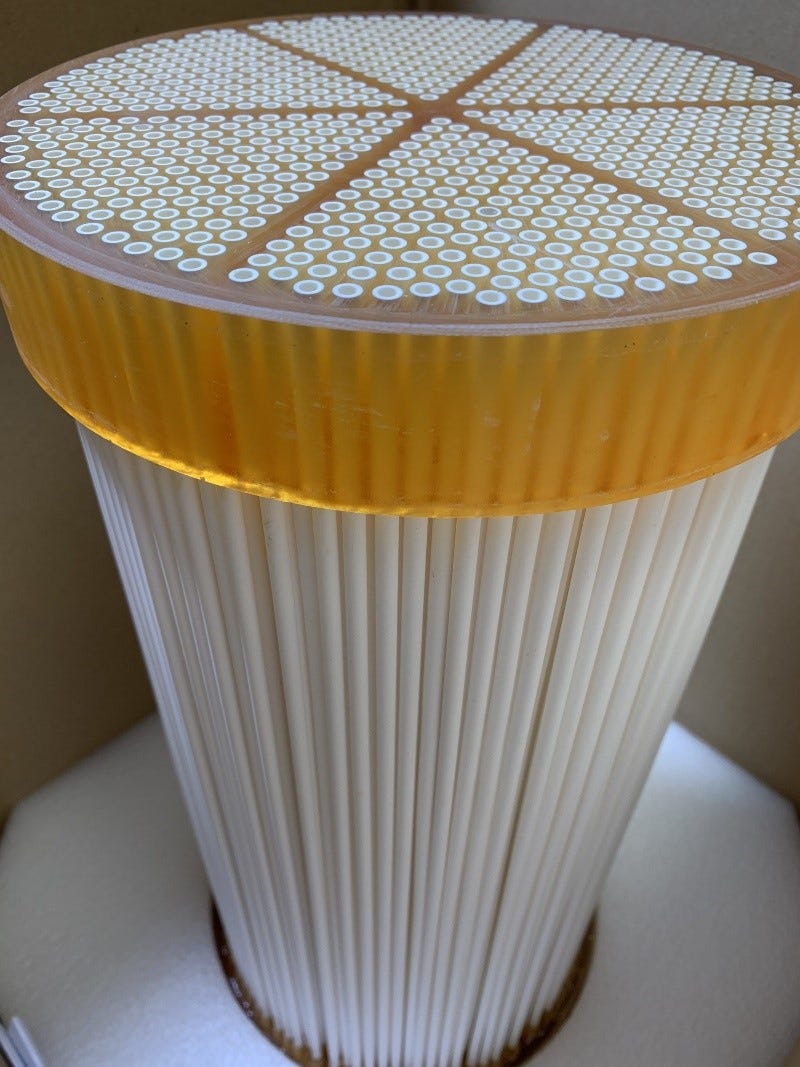
Each CO2 capillary is a vertical hollow fiber membrane tube that contains the circulating solvent.
Hollow fiber membrane tubing.
The CCT has 3,140 blades, each having a 10m2 surface area. This gives the CCT a total functional surface area of 31,400 m2.
The blades are 4m tall, and the CCT is 5m tall. This allows 1m to house the equipment for solvent regeneration. This is the usual equipment common to solvent-based DAC - 900 °C calciners, pellet reactors, oxy generators, etc. (just kidding 😉)
A CCT tree is built by stacking multiple toruses on top of each other with 5m gaps between them. This makes the tree about 100m tall. Each CCT tree will have 10 CCTs. This gives each tree 314,000m2 of surface area in contact with the air.
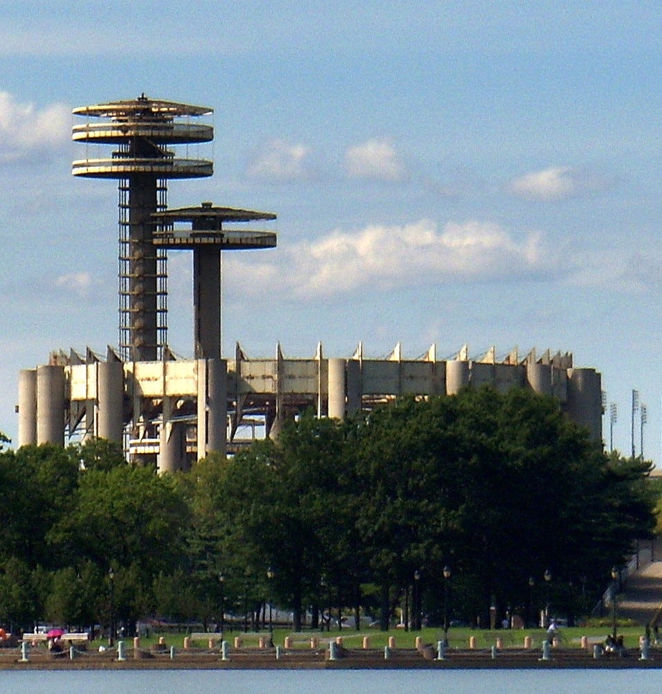
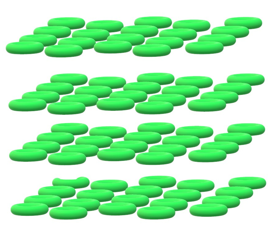
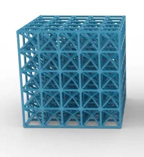
The goal is to create a 3D array of hundreds of CCTs in a modestly compact space. If this seems somewhat familiar, you might be thinking of the 1964 World's Fair.
CO2 capturing pre-prototype at the 1964 World’s Fair in NYC.
Forest of Floating CO2 Capturing Toruses
While each CCT and each CCT Tree operate independently, the CCT Trees depend on the forest for structural strength. Each CCT will have 3 vertical support columns. This will accommodate the stacked design and allow the weight of the 10 CCTs to be firmly supported at the ground. But, being tall structures, additional support is required to withstand the force of high winds during intense storms. This extra support will come from structural interconnects between the vertical columns of one tree and the neighboring trees. The structural interconnects will use all three dimensions. This will form a robust lattice structure.
The Forest is Stronger than the Tree
Biomimetic sighting - Stomata
The exterior of the CCT will protect the CCT interior from sunlight and excess wind. A light baffle will allow air to flow freely but will prevent light from passing into the CCT. Fine netting will create a barrier to birds and most bugs. The outermost edge of the CCT will be vertically arranged adjustable shutters. These shutters will open and close in response to ambient wind. These shutters will prevent excess winds from damaging the fragile equipment inside the CCT. These shutters will operate as a biomimetic to the stomata found in leaves. Stomata regulate the gas exchange and work to prevent damage to the delicate structures of the leaf.
For this design, inner and outer shutters will regulate air flowing through the CCT and protect the delicate tubing from high winds.
One consideration of this design is to avoid Sherwood's Rule by maintaining a high pCO2 throughout the segment. Air will flow freely between the tubes in the blades. CO2 near the CO2 capillary will diffuse across the capillary membrane and be absorbed by the solvent.
Under low wind conditions, there will be a pCO2 gradient within the blade, with the minimum pCO2 found in the interior of the blade. The solvent will have a CO2 capture rate as it travels through the tubing. The solvent should always be able to capture CO2 when the local pCO2 is above 50% of ambient.
Biomimetic sighting - Variable Solvent Flow
With variable wind speed, there will be a wind velocity such that pCO2 is constant and high throughout the interior of the blades. Higher wind velocities will replace captured CO2 quicker. This design will exploit the kinetic energy of wind to achieve optimal mass transport.
The shutters will regulate air flow and mass transport in response to external conditions.
In addition to the shutters adjusting to wind conditions, the solvent flow will be variable. With dead, still air, the solvent will flow slowly. When wind speeds are high, the solvent will flow at a faster rate to maximize mass transport for the energy being consumed. Monitoring pCO2 and windspeed will allow for dynamic adjustment of the solvent's velocity.
This ability to regulate solvent velocity is very much like the human respiratory system. The heart beats faster to meet the needs of gas transport. This design will provide the capability to utilize wind energy directly. Stronger winds are harnessed without various energy losses, without killing birds, and without the need for battery storage.
Vents and channels will be added to promote air circulation inside the CCT. The CO2 capillaries will provide resistance to the wind, so air channels will allow air to flow effortlessly into the CCT's interior.
Co-Benefits
Many CO2 technologies have co-benefits that make the technology more valuable. One popular co-benefit is the large number of jobs created by the technology's deployment and operation. My CO2 capture technology has no co-benefits. It only removes CO2 from the air. While the CCT Tree will require some construction workers to build the forest, the CCT blades are mass-produced in an automated factory.
CCT assembly will also be automated. The CCT tree will be designed such that a robotic entity can climb the tree using the support columns. The robot will install all the blades (3140) without human assistance.
This same robot will perform maintenance. Sensors will monitor system health and productivity. As there are no field serviceable parts, the robot will replace a blade when a failure is detected. More durable parts (calciners, pellet reactors, pumps, etc.) can also be replaced by the robot.
Production Performance
I have not yet worked out the specific performance. Naturally, the goal is to capture the maximum amount of CO2 while optimizing for energy use and time. Evaluating the ability of a single CCT to remove 1 ton of CO2 per day requires the CO2 flux into the CO2 capillary to be at least 8.34 x 10⁻⁶ moles per second. This seems small, so 1 ton per day per CCT is achievable.
Using data from published research, one megaton of CO2 can be captured per year using 50 million m2 contactor surface area (unknown wind effects). Since CO2 in the air is dilute, CO2 in the air is likely the mass transfer bottleneck. A CCT is 31,400 m2, and 1,600 CCTs will capture a megaton of CO2 annually. The daily capture rate is 1.71 tons per day per CCT. A tree with 10 CCTs will capture 17.1 tons daily, which is 6240 tons annually.
For comparison, Carbon Engineering uses 38,000 m2 of surface area and fans to capture 1 mt of CO2 annually.
169 CCT trees containing 1,690 CCTs placed in an array and spaced 40 meters apart will require a surface area of 560m x 560m (= 0.32 km2) to capture 1.05 megatons of CO2 annually. Taller trees, with more CCTs, will require less surface area.
Siting
This technology is designed to be powered by methane, which is combusted to produce electricity. Close proximity to methane production will be very beneficial to eliminate methane leakage. The methane can be piped to the forest or combusted on-site, and the electricity is transmitted to the forest. This technology will consume water, so a source of fresh water is required. The best source of freshwater is likely to be desalinated seawater, so the forest should be located somewhat close to a coastline. The captured CO2 must also be stored in a suitable geological formation.
These factors make Texas an ideal location in the US for a vast CCT forest. Over time, natural gas usage can be reduced, and solar energy from the Texas deserts would then power the CO2 removal forests. The most significant engineering challenge will be to make the tall CCT trees strong enough to survive powerful hurricanes.
Conclusion
Once built and with routine but minimal maintenance, a CO2-capturing forest will remove CO2 from the air for centuries.
An energy-efficient pathway to achieve gigaton scale CDR is increasingly apparent as it can now be visualized as well as computationally analyzed. The best plan is to continue funding horrible CO2 capture technologies and wait a few decades until the warming problem is terrible. Then, it will be an ideal time to begin developing a methane-powered CDR technology.


hi- sorry- this seems dubious. one man rube goldberg system. if you actually make a working model- send me the data. i will reconsider giving money. in the meanwhile you should look at : Graphyte takes waste biomass like discarded wood residue or rice hulls, dries and sterilizes it to prevent decomposition.
--It then condenses it into dense carbon blocks, wraps it in a proprietary polymer barrier and stores it underground in an engineered storage site. The carbon within will be locked away and prevented from being re-released.
What appealed to Rivest about this approach was its potential for durable, affordable and immediately-scaleable carbon removal. “There’s a concern around the energy and capital intensity of some of the existing approaches, particularly the engineered approaches,”..
Graphyte plans on buying waste biomass from local sources and selling its carbon removal services to corporate buyer